It’s probably fair to say that very few guitar techs enjoy doing wiring work on Gibson semis. I attempted a repair on my old ES-330 for the first time a few decades ago. It took me about an hour to get the loom out and a fortnight to put it back in…
Some compare the task to putting a ship in a bottle, but once you know a few tricks and techniques, it can make wiring a little easier than you think.
Our subject is a late-’00s Gibson ES-335 with scratchy potentiometers and tone controls with no audible effect unless they’re almost completely backed off.
Latest Videos FromGuitar World
James, the guitar’s owner, decided it would benefit from a new wiring harness with Armstrong Music’s Premium 450 Series 550k potentiometers and a pair of Sprague Black Beauty replica capacitors from Luxe Radio.
Pulling Rank
Taking out a harness from any guitar of this sort begins with removing the strings, tailpiece, bridge and pickguard. If you aren’t able to measure and make a note of the action prior to disassembly (or you forget to do it), place some masking tape over the bridge-post thumbwheels to hold them in place.
Removing control knobs can be tricky, especially when they’re pressed tightly onto the pot shafts or there’s insufficient space to get the tips of your fingers underneath them. There are tools designed for the job, but I lever them up using a pair of teaspoons. If you try this, just remember to place some thick cardboard or, better still, cork tile between the spoons and the guitar body or you’ll probably end up with some nasty dents.
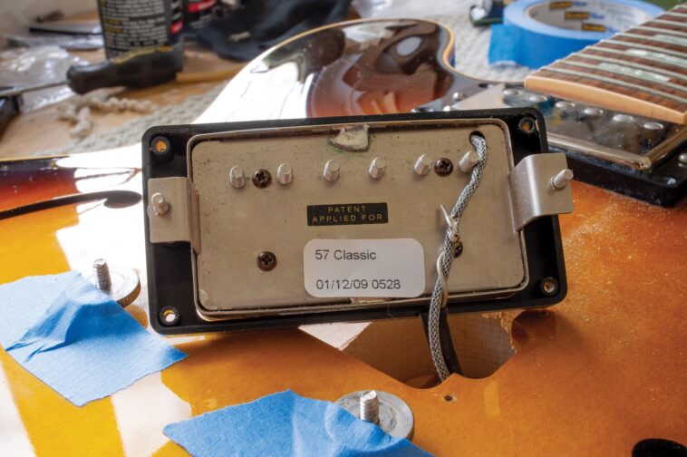
Undo the nuts holding the potentiometers and output jack, along with the ring nut securing the switch, and the harness should drop down inside the body. But before you can remove it, the ground wire will need to be disconnected. It’s usually soldered to the braiding of the bridge pickup’s leadout wire, so remove the four pickup ring screws, lift out the pickup and you should find the joint.
All the latest guitar news, interviews, lessons, reviews, deals and more, direct to your inbox!
The wire is sometimes quite stiff and wrapped around the pickup wire, so you’ll need to unwrap it very carefully as you melt the solder. You might also want to place something over the guitar while you’re working to protect the finish from blobs of molten solder.

By looking inside the bridge pickup cavity, you’ll discover if it’s possible to pull the harness out through the pickup hole. On this guitar there was a wide gap through the centre block into the body, but some semi-solids will only have a narrow hole for the pickup wire. If that’s the case, the harness will have to be taken out through the treble-side f-hole.
Using my fingers and a wooden dowel, I coaxed the switch towards the pickup cavity. This pulled the neck-pickup control pots out, too, followed by the jack socket and, finally, the bridge-pickup pots. If things get tangled with the pickup wires, back up and move the wires out of the way. If things get snagged, stay calm, back up and think it through, rather than try to force anything.

With the full harness resting on top of the guitar, I de-soldered the pickup wires from the volume potentiometers and lifted it clear. Had we been keeping the original pickups, I would have left the neck pickup in place, but James was also upgrading the pickups so I removed them both.
Soldering On
Wiring up Teles, Strats, SGs and Les Pauls and so forth is relatively easy because you can attach the switches and pots to the body, plate or pickguard before soldering everything up. You can’t do that with Gibson thinlines or most other hollowbody guitars, but getting the component spacing correct is crucial for easy harness installation.
The solution is to make a template. I started by placing a sheet of A4 over the holes in the body and pressing down with my finger to make indentations in the paper. Although basic, it’s a quick and accurate way to register the control layout positions, and I marked the centre of each indentation with a pencil.

Placing the paper over a piece of MDF, I pressed a spike through all the pencil dots to transfer the layout. I then drilled holes through the MDF so I could mount and secure the socket, potentiometers and switch onto it before assembling the new wiring harness. For the jack socket and pots you’ll need a 9.5mm or 10mm bit, and a 14mm bit or step cutter for the switch.
I used MDF, which isn’t ideal as it’s too soft and powdery, so next time I’ll use Perspex instead. Since the harness has to be assembled from the ‘underside’, it makes sense to mark each template hole both front and back to avoid confusion.

Harnessing Up
Although the potentiometers James had provided were all nominally 550k, the stated value and the actual value rarely coincide. You can measure the true value of any potentiometer by taking a resistance reading across the outer solder tags. In my experience, vintage 500k pots tend to read way higher than 500k, and are sometimes closer to 600k.
If you want a little less mud from a neck pickup, use the pot with the highest actual value in the neck volume position. Conversely, you can use the pot with the lowest value for the bridge volume if it sounds a bit bright. Three of these pots read between 515k and 519k, and one was 529k.

With the switch, jack socket and all the pots mounted onto the template, it was time to start assembling the harness. While it might have been possible to install the harness through the bridge-pickup cavity, I prefer to go through the f-hole, and over the years I have learned a couple of things that make it easier.
Inside Track
The first trick is to solder the braided wires to the sides of the pot casings, rather than the backs. It’s hard to pinpoint when Gibson started doing this, but I discovered it when reassembling a chopped-up harness from a 1964 ES-335.

Getting potentiometers through an f-hole requires a twisting motion and there is relatively little wiggle room.
When the braided wires are soldered to the rear of the pot casings it can be an even tighter fit, but when they’re attached to the sides, it’s almost as if they aren’t there.
The second trick is to increase the length of the wires running from the neck tone control to the jack socket, and between the neck pickup controls and the bridge pickup controls. Just look at the photo of the assembled harness to see what I mean.
I do this because I prefer to install the harness in stages, rather than try to get it in all at once. Some guitar techs thread twine or string through the holes, tie it onto the parts and then pull them into position. The same can be done using surgical tubing, but I’ve ended up with a tangled mess whenever I’ve attempted this.

Instead, I started by getting the jack socket fixed in position while the rest of the components remained outside the body. To do this, I threaded some braided cable through the socket hole and pulled it out through the f-hole. I popped a star washer over the wire, pushed the wire through the socket and then tied a knot.
The star washer and socket went through the f-hole into the body, and I tugged the braided wire to pull them both into position. Maintaining tension, I ran a washer and nut down the wire before tightening everything up. So long as you’ve used enough wire for it still to be accessible at the f-hole, you can pull it out and phase one is complete.
Before installing the neck pickup controls, the pickup itself must be connected to the volume pot. I threaded the pickup wire through the f-hole and ensured there was plenty of protection between the pot and the paintwork while I made the solder joints. With that done, the switch and the neck pickup controls went in through the f-hole, too.

Once they were inside, I popped on star washers to prevent things from twisting around – you can use your fingers to manoeuvre the switch into position before securing it with its ring nut. You can do the same with the volume pot, but the tone pot is always just out of reach and out of sight.
When a harness is assembled on a template, you can be confident that the pot shaft will be within the vicinity of the hole. I manoeuvred the pot using a piece of dowel until the shaft was visible through the hole and I grabbed it using long tweezers to pull it through.
From here it’s straightforward – just solder the bridge pickup to the volume pot and push the pots through the f-hole. Both pots will remain within easy reach and you can lever them up through the holes using your finger to complete the installation.

Back In Control
The extra wire length on the harness is probably equivalent to a couple of pedalboard patch cables, so that doesn’t concern me. In addition to making the harness installation far easier, the volume pots can be taken out individually for cleaning or pickup swaps without having to remove the entire harness.
Despite only doing this job maybe once a year, I’m no longer daunted by it and these days it takes me closer to 45 minutes than a fortnight. Give it a go!